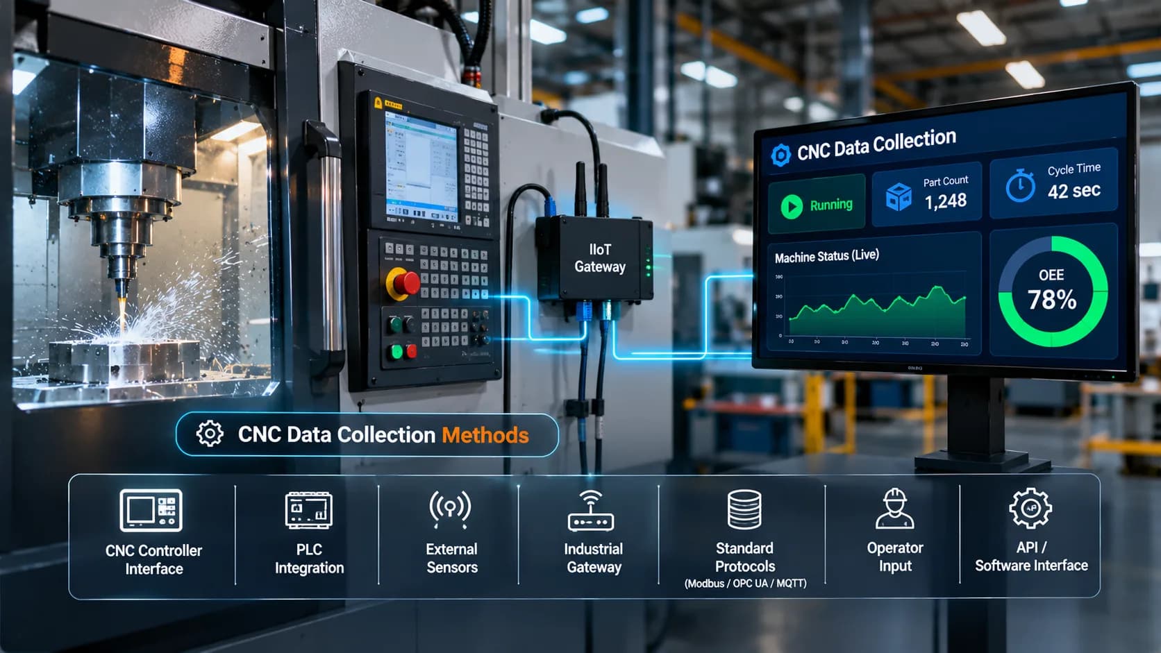
CNC Data Collection Methods: A Complete Guide for Modern Manufacturing
Modern manufacturing depends on accurate, timely, and accessible production data. CNC machines generate valuable information throughout their operating cycles, including machine status, cycle time, part counts, alarms, program details, and production performance. However, collecting this information consistently across different machines can be challenging, particularly when a factory operates equipment from multiple manufacturers or uses a combination of modern and legacy CNC controllers.
CNC data collection is the process of capturing machine-level information, transferring it to a central system, and converting it into useful production insights. It provides manufacturers with visibility into how equipment operates, where production interruptions occur, and how effectively machines are being utilized.
With industrial IoT technologies, manufacturers can collect CNC machine data through controller interfaces, PLCs, external sensors, communication protocols, and industrial gateways. The right approach depends on the machine's capabilities, the required data points, and the existing factory infrastructure.
This guide explains the most common CNC data collection methods, the information manufacturers can capture, and how to build a reliable data collection system for a connected manufacturing environment.
What Is CNC Data Collection?
CNC data collection refers to the automated or semi-automated capture of operational information from Computer Numerical Control machines.
A CNC machine produces information during different stages of its operation. Some information is available directly from the machine controller, while other data must be collected through connected PLCs, sensors, or operator inputs.
A data collection system brings these different sources together so manufacturers can monitor machine activity from a centralized platform.
Common information collected from CNC machines includes:
Machine running, idle, stopped, and alarm conditions
Production quantities and completed part counts
Cycle time and machining duration
Job and program information
Machine alarms and operating events
Planned and unplanned downtime
Tool usage and selected tool-condition indicators
Operator-entered production and rejection information
Energy consumption, where suitable metering is installed
The objective is not simply to collect more data. It is to capture the right information accurately, associate it with the correct machine and production context, and make it available for operational decisions.
Why Is CNC Machine Data Collection Important?
Without reliable machine data, production teams often depend on manual reporting, operator observations, and periodic inspections to understand factory performance.
These methods can create delays and inconsistencies. A machine may remain idle for an extended period without the production team receiving timely information. Part counts may be recorded incorrectly, and the reasons behind production interruptions may not be documented consistently.
Automated CNC data collection helps address these limitations.
1. Real-Time Machine Visibility
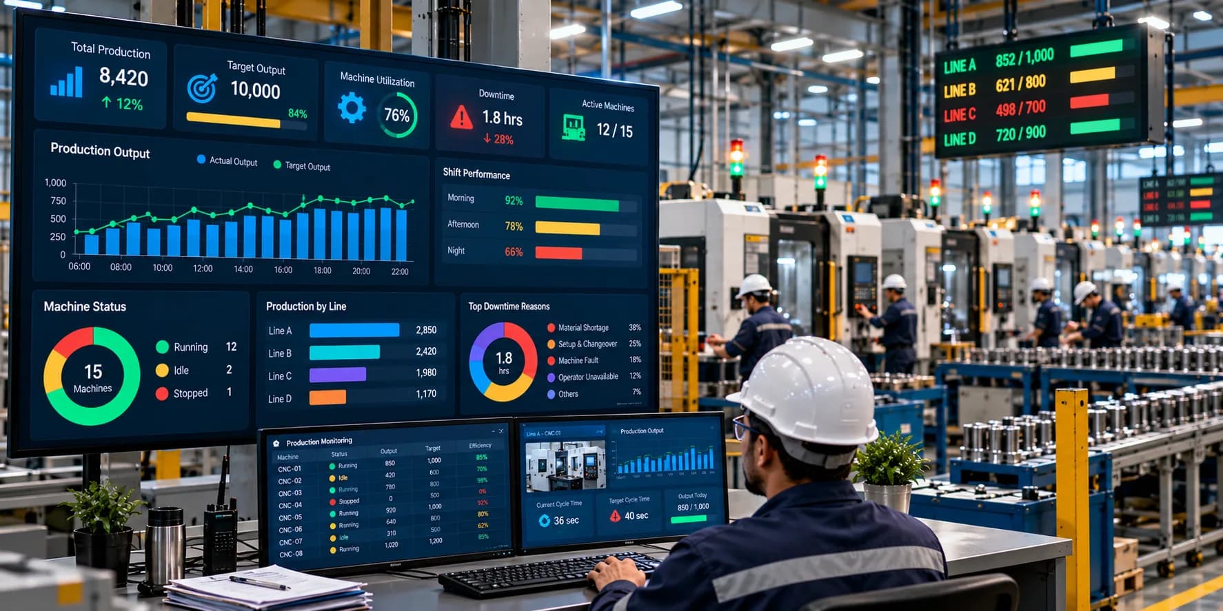
Manufacturers can monitor machine operating conditions without repeatedly checking equipment on the shop floor.
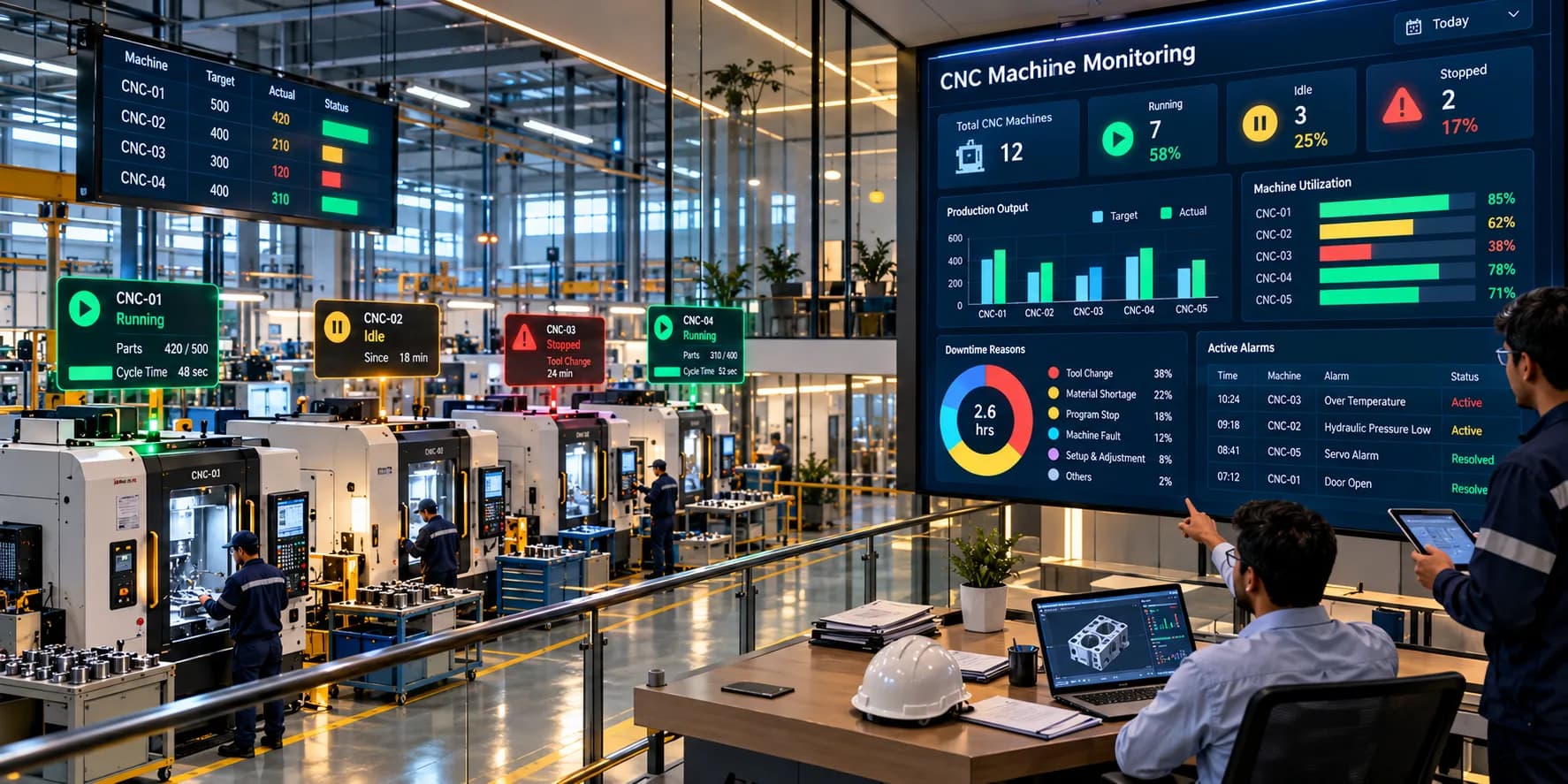
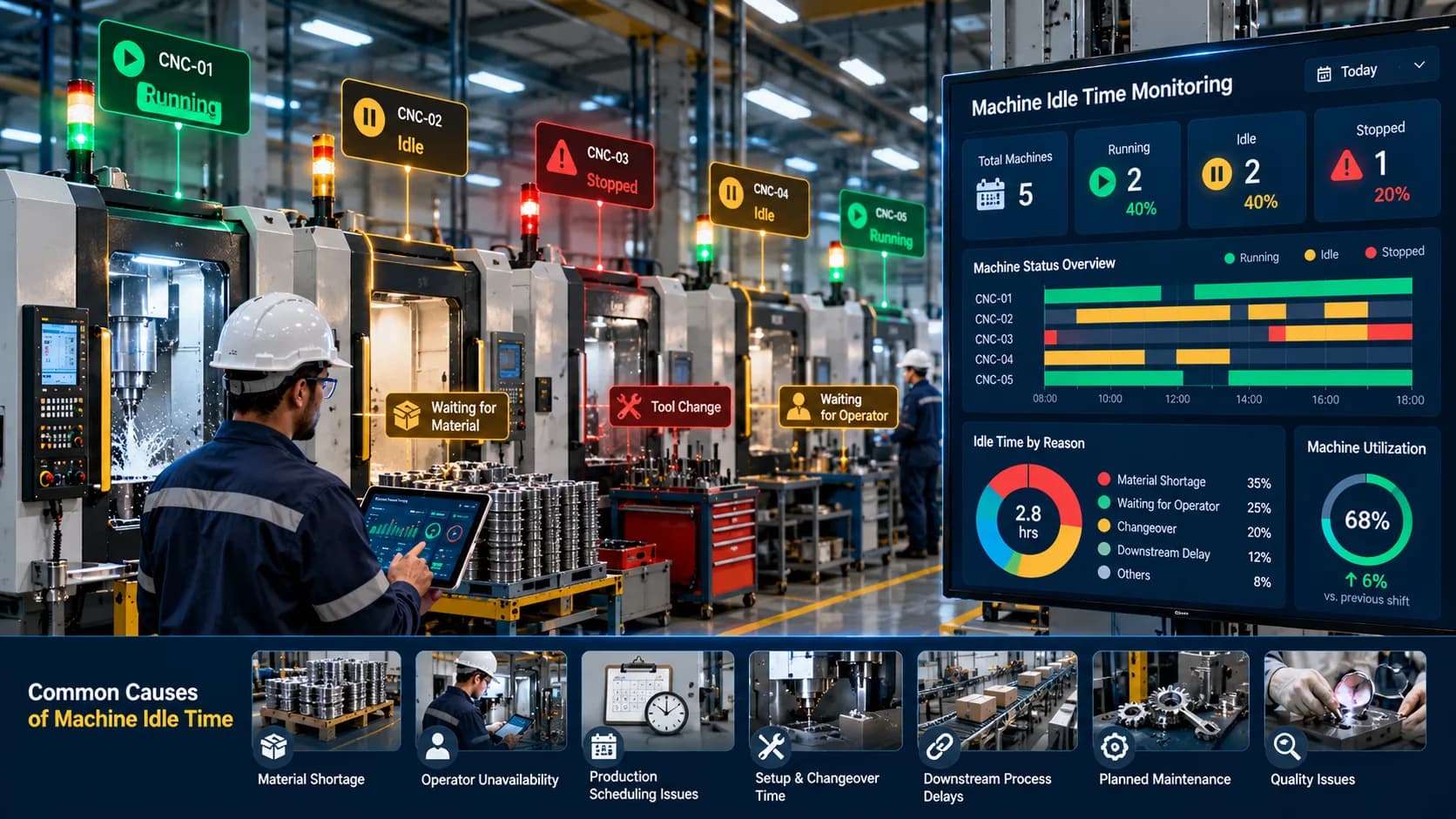
Production teams can identify which machines are running, idle, stopped, or experiencing alarms. This information supports faster responses to operational interruptions.
2. Accurate Production Tracking
Machine signals and controller information can be used to capture completed production quantities.
Instead of relying entirely on manual counting, manufacturers can collect part counts from controller counters, cycle-complete signals, or other suitable machine outputs.
3. Better Downtime Identification
Machine-state information helps identify when equipment stops operating.
When combined with operator-entered downtime reasons, the collected data can help distinguish between maintenance issues, material shortages, setup delays, quality problems, and other production interruptions.
4. Improved Production Analysis
Historical machine data helps production managers compare actual operating performance across shifts, machines, and production orders.
It also provides the foundation for analysing machine utilization, cycle time, production output, and Overall Equipment Effectiveness.
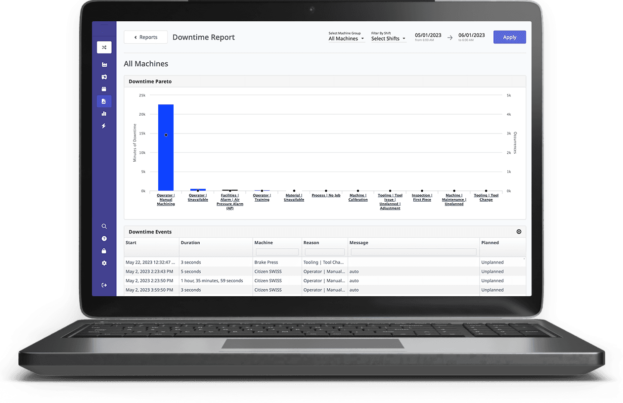
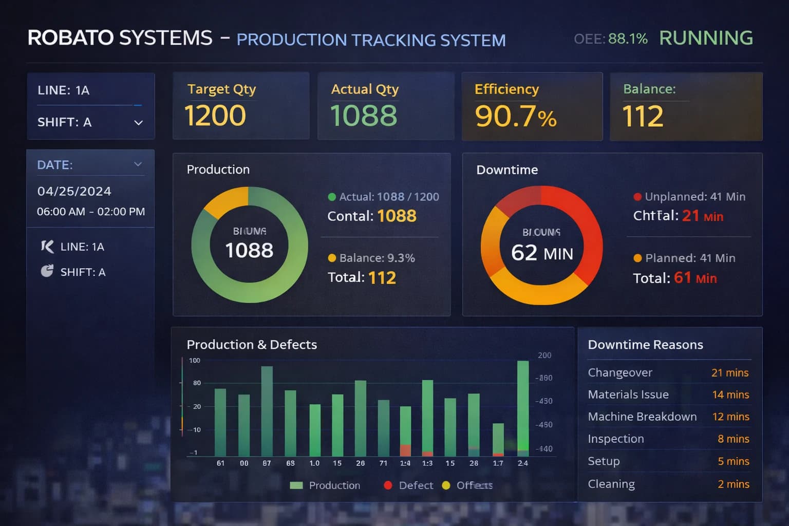
Manufacturers looking to connect machine-level information with production reporting can explore Robato's production monitoring solution.
7 Common CNC Data Collection Methods
There is no single collection method suitable for every CNC machine. The most appropriate approach depends on the controller model, machine age, available interfaces, required information, and integration requirements.
The following methods are commonly used in industrial environments.
1. CNC Controller Data Collection
Collecting data directly from the CNC controller is often the most comprehensive approach when the controller provides suitable communication interfaces.
The controller manages machine programs, operating modes, alarms, machining cycles, and other operational information. Depending on the controller manufacturer and model, selected data may be accessible through native communication interfaces, software libraries, APIs, or supported industrial standards.
Information that may be available includes:
Machine operating status
Active program or job number
Current machining cycle
Part counter values
Cycle time information
Controller alarms and messages
Selected tool and operating parameters
How it works:
Identify the CNC controller manufacturer and model.
Check the available communication interfaces and supported data points.
Establish an authorized connection using the appropriate interface.
Configure the required data collection and update frequency.
Transfer the collected information to an edge gateway or monitoring platform.
Controller-based collection is particularly useful when manufacturers require detailed machine information rather than only basic running and stopped signals.
However, available data varies between controller generations and manufacturers. Some machines may require additional hardware, licensed software options, or protocol converters.
2. PLC-Based Data Collection
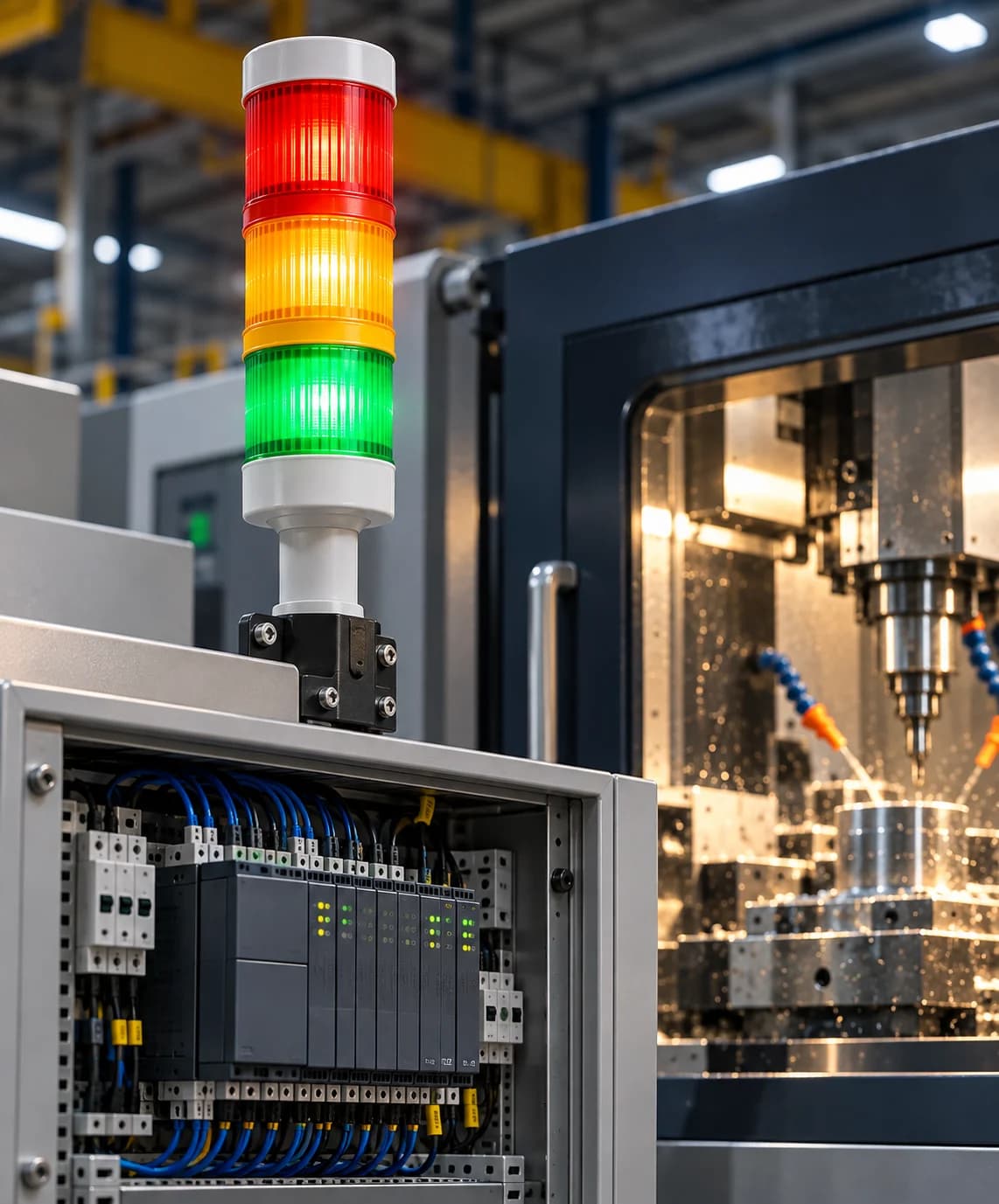
Programmable Logic Controllers are widely used in manufacturing automation. They manage machine sequences, input/output signals, safety-related logic, and interactions with production equipment.
A PLC can also provide useful information for machine monitoring.
For example, a CNC machine may expose signals indicating:
Machine cycle active
Cycle complete
Machine ready
Fault or alarm condition
Door open or closed
Part detection
Production counter updates
A connected data acquisition system can read suitable PLC tags or signals and transmit them to a central monitoring application.
How PLC-based collection works:
Identify the PLC connected to the CNC machine.
Determine which machine signals and tags are available.
Confirm the communication protocol and access permissions.
Connect an industrial gateway or compatible monitoring device.
Map the signals to meaningful machine states and production events.
PLC-based collection is especially useful when controller-level integration is unavailable or when the required information is already exposed through the machine's automation system.
One important consideration is that PLC signals must be interpreted correctly. For example, a cycle-active signal may indicate that the machine is executing a program, but it does not necessarily confirm that a finished part has passed quality inspection.
3. External Sensor-Based Data Collection
External sensors provide another practical method of collecting machine information.
They are particularly valuable for older CNC machines that do not support modern communication interfaces or do not expose the required data points.
Sensors can be installed at suitable locations to capture physical machine activity.
Common sensor types include:
| Sensor Type | Information Collected | Typical Application |
|---|---|---|
| Proximity sensor | Object or position detection | Detecting machine or part movement |
| Optical sensor | Object presence and detection | Counting completed parts |
| Current sensor | Electrical current variations | Supporting machine activity detection |
| Encoder | Rotation, position, or speed | Measuring movement or rotational activity |
| Vibration sensor | Vibration patterns | Monitoring selected machine conditions |
| Temperature sensor | Temperature readings | Monitoring equipment or component temperature |
Example:
An optical sensor can be installed at a suitable part-discharge location. Whenever a completed component passes the sensor, the system generates a detection signal that can be used to update a production counter.
Similarly, an electrical current sensor can provide information about changes in machine load. When properly configured and validated, this information may help distinguish operating conditions.
However, current consumption alone should not automatically be treated as proof of production. Machine idle loads, spindle activity, auxiliary systems, and different machining operations can produce overlapping electrical patterns.
Sensor-based collection is flexible, but installation, calibration, signal filtering, and validation are important for maintaining data accuracy.
4. Industrial IoT Gateway-Based Collection
Industrial IoT gateways connect machine-level equipment with monitoring platforms and enterprise applications.
They act as an integration layer between different industrial data sources and communication technologies.
A gateway may collect information from:
CNC controllers
PLCs
Industrial sensors
Digital input/output modules
Energy meters
Other connected production equipment
After collecting the information, the gateway can process, standardize, buffer, and transmit selected data to a local server or cloud-based application.
Typical gateway workflow:
Collect signals or data from connected machines.
Convert information into a consistent data structure.
Associate readings with machine identifiers and timestamps.
Apply local filtering or processing where required.
Transmit the data to the monitoring platform.
Buffer information temporarily if network connectivity is interrupted.
Gateways are particularly useful in factories with different machine manufacturers, communication interfaces, and generations of equipment.
They can reduce integration complexity by providing a common connection point between shop-floor devices and higher-level applications.
5. MTConnect-Based CNC Data Collection
MTConnect is an open manufacturing equipment interoperability standard designed to make machine information easier to access and interpret across different industrial systems.
It defines a structured information model for representing manufacturing equipment data.
In a typical implementation, an MTConnect agent exposes equipment information through an HTTP-based interface. Applications can request this information and receive structured representations, commonly in XML or JSON depending on the implementation.
MTConnect can help collect information such as:
Machine execution state
Operating mode
Spindle information
Feed rate
Program-related information
Alarms and events
Selected production-related values
The availability of information depends on the equipment, adapter, and implementation.
Important: MTConnect is not a sensor or a fieldbus. It is an interoperability standard and information model. A machine may require an adapter or additional integration layer before its data can be exposed through MTConnect.
It is useful when manufacturers want a more standardized way to access information from supported equipment.
6. OPC UA-Based CNC Data Collection
OPC UA, or Open Platform Communications Unified Architecture, is an industrial communication architecture used to exchange information securely between machines, controllers, gateways, and software applications.
It supports structured information models and different communication patterns, including client-server and publish-subscribe configurations.
In CNC monitoring environments, OPC UA can be used to exchange machine data when the controller, PLC, or gateway supports the required OPC UA functionality.
Depending on the implementation, information may include:
Machine operating states
Production signals
Alarm information
Process variables
Equipment parameters
Selected production counters
OPC UA also provides security capabilities such as authentication, encryption, and certificate-based trust mechanisms. These capabilities must be configured correctly as part of the integration.
Not every CNC controller provides native OPC UA support. Some installations require a compatible PLC, gateway, or software component to expose machine information through OPC UA.
For factories integrating different industrial systems, OPC UA can provide a structured approach to machine-to-application communication.
7. Manual and Operator-Based Data Collection
Automated collection provides valuable machine information, but not every production event can be identified reliably through controller signals or sensors.
Some information requires human input.
Examples include:
Downtime reason
Setup or changeover activity
Material shortage
Tool replacement
Quality rejection
Maintenance intervention
Production order changes
An operator can enter these details through a touchscreen, machine terminal, tablet, or connected production application.
For example, a machine monitoring system may automatically detect that a CNC machine has stopped. The operator can then select the reason for the interruption from a predefined list.
Combining automatic machine-state detection with operator-entered context provides a more complete production record.
Manual inputs should be designed to be simple and consistent. Too many fields or complicated entry procedures can reduce adoption and create incomplete records.
CNC Data Collection Methods: Comparison
Different collection methods provide different levels of detail, flexibility, and integration complexity.
| Collection Method | Best Suited For | Key Consideration |
|---|---|---|
| CNC controller interface | Detailed machine and program data | Depends on controller compatibility |
| PLC-based collection | Machine states and automation signals | Requires correct tag mapping |
| External sensors | Legacy machines and physical events | Requires installation and validation |
| IoT gateways | Connecting multiple data sources | Requires protocol and device configuration |
| MTConnect | Standardized equipment information | Requires a supported implementation |
| OPC UA | Structured industrial communication | Requires compatible endpoints and security configuration |
| Operator input | Downtime reasons and production context | Depends on consistent data entry |
In many factories, the most effective solution combines multiple methods rather than depending on one source.
For example, controller data may provide program and cycle information, PLC signals may indicate machine states, and operator inputs may explain why production stopped.
What Types of Data Should Be Collected from CNC Machines?
A successful CNC data collection system should focus on information that supports actual production decisions.
Collecting unnecessary information can increase system complexity without improving operational visibility.
The following categories are useful starting points.
1. Machine Status Data
Machine status data shows the current operating condition of the equipment.
Typical states include:
Running
Idle
Stopped
Alarm
Setup
Maintenance
These states may be obtained directly from a controller or PLC, or derived from multiple signals.
Manufacturers should define clear state rules so that the same machine condition is interpreted consistently across the monitoring platform.
2. Production Count Data
Production count data tracks the number of components produced by a machine.
It can be collected from controller counters, PLC registers, cycle-complete pulses, or suitable part-detection sensors.
Important considerations include:
Whether the counter records cycles or individual parts
Whether one cycle produces multiple components
How counter resets are handled
How rejected parts are recorded
How production quantities are associated with orders and shifts
These details help prevent inaccurate production reporting.
3. Cycle Time Data
Cycle time represents the duration required to complete a production cycle.
It can be captured from controller data or calculated using appropriate cycle-start and cycle-complete events.
Monitoring cycle time helps manufacturers compare actual production behaviour against expected cycle times.
However, the definition of a cycle should be consistent. Different products, programs, and machining operations may have different expected durations.
4. Alarm and Event Data
CNC controllers can generate alarms and event messages related to equipment conditions.
Collecting these events helps maintenance and production teams understand when interruptions occur and identify recurring issues.
Useful information may include:
Alarm code
Alarm description
Machine identifier
Event timestamp
Duration of the condition
Reset or recovery time, where available
Alarm data should be interpreted in the context of the machine and its operating process.
5. Tool and Machine Condition Data
Some CNC installations expose information related to tool usage, spindle load, vibration, temperature, and other operating parameters.
This data can support condition monitoring and maintenance analysis.
For example, changes in vibration or spindle load may indicate a condition worth investigating. However, these measurements need suitable baselines, context, and engineering interpretation before being treated as evidence of a developing fault.
6. Energy Consumption Data
Energy meters and suitable power-monitoring devices can capture electrical consumption.
When energy information is associated with machine operating states and production quantities, manufacturers can analyse energy usage across different operating conditions.
Useful measurements may include:
Energy consumption
Power demand
Voltage
Current
Power factor
The available measurements depend on the installed metering equipment.
Industrial Protocols Used in CNC Data Collection
Communication protocols determine how data moves between controllers, PLCs, gateways, and monitoring applications.
The right protocol depends on device compatibility, the information model, network architecture, and security requirements.
Modbus
Modbus is an industrial communication protocol commonly used to exchange data with PLCs, meters, and other automation devices.
It is often used for reading registers and digital or analog values.
Modbus TCP operates over Ethernet, while Modbus RTU is commonly used over serial communication.
It is important to understand that Modbus provides a communication method; the meaning of individual registers must be defined and mapped correctly.
MQTT
MQTT is a lightweight publish-subscribe messaging protocol frequently used in IoT architectures.
A device or gateway can publish machine information to a broker, while applications subscribe to the topics they need.
MQTT can be useful for transmitting machine data from edge gateways to cloud or centralized applications.
It is not a replacement for every controller-level industrial protocol. In many implementations, a gateway first collects data through another interface and then publishes selected information using MQTT.
MTConnect
MTConnect provides a structured model for manufacturing equipment information and commonly exposes data through an HTTP-based agent interface.
It is particularly relevant when equipment or adapters support the standard.
OPC UA
OPC UA provides industrial interoperability through structured information models and secure communication mechanisms.
It can be used for communication between supported CNC-related equipment, PLCs, gateways, and software systems.
These technologies are not interchangeable. A factory may use Modbus or a controller-specific interface to collect machine data, OPC UA to exchange structured industrial information, MTConnect to expose standardized equipment data, and MQTT to deliver selected readings to an IoT platform.
How to Build a CNC Data Collection Architecture
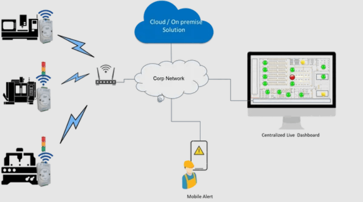
A reliable architecture should connect shop-floor equipment to monitoring software while maintaining data consistency and operational security.
A typical architecture contains five layers.
Layer 1: CNC Machines and Data Sources
This layer includes CNC machines, controllers, PLCs, sensors, meters, and other connected equipment.
Each source provides specific information depending on its capabilities.
Layer 2: Data Acquisition
This layer captures information through controller interfaces, PLC connections, industrial protocols, and sensor signals.
The collection method should match the data source and required level of detail.
Layer 3: Edge Gateway and Data Processing
An industrial gateway collects information from multiple devices and prepares it for transfer.
Typical responsibilities include:
Protocol conversion
Data normalization
Timestamp handling
Signal filtering
Local buffering
Machine identification
Edge processing can also help reduce unnecessary network traffic by transmitting relevant changes or selected readings.
Layer 4: Centralized Monitoring Platform
The monitoring platform receives and stores machine data.
It associates readings with machine identifiers, production shifts, timestamps, and other available production context.
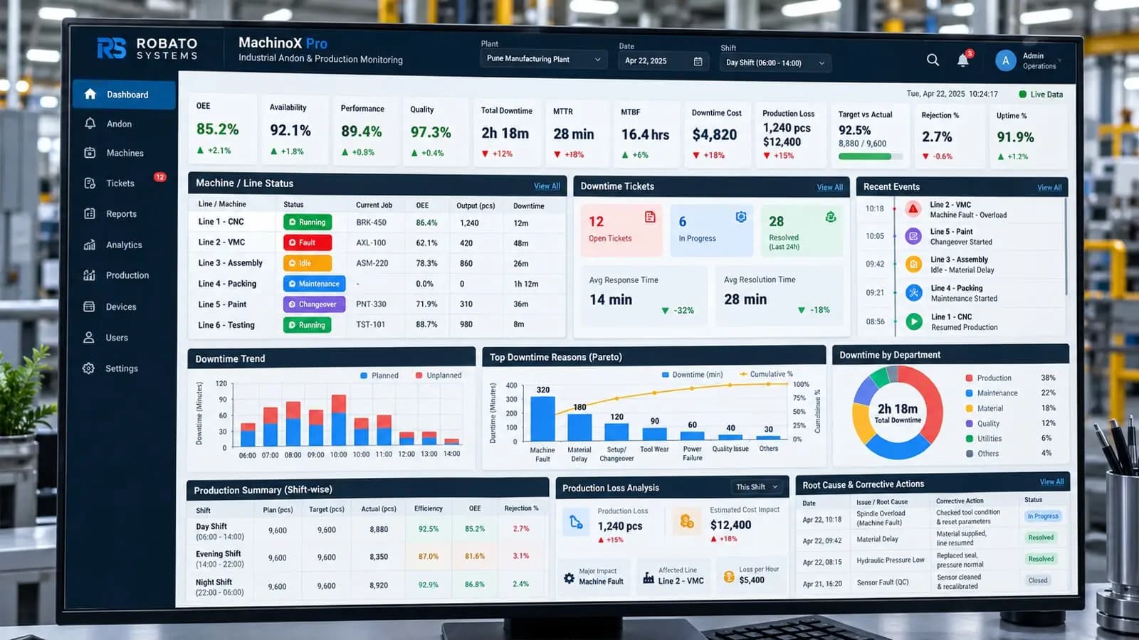
The system can then generate reports, dashboards, alerts, and historical trends.
Layer 5: Production Dashboards and Analytics
The final layer presents useful information to production managers, supervisors, maintenance teams, and operators.
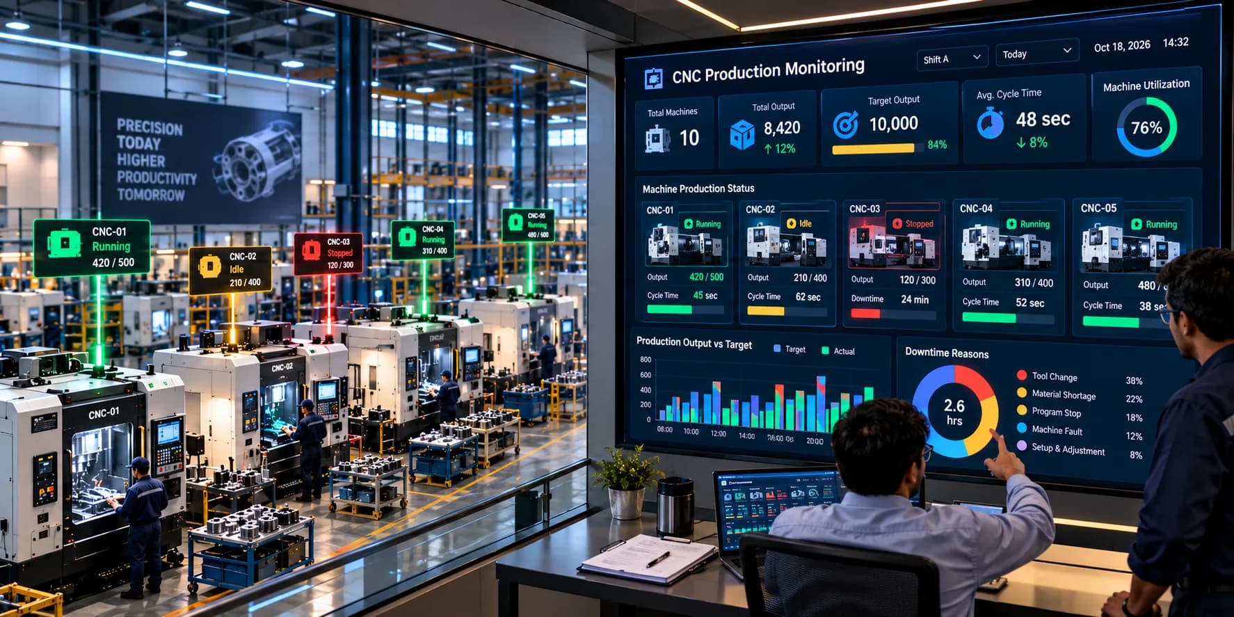
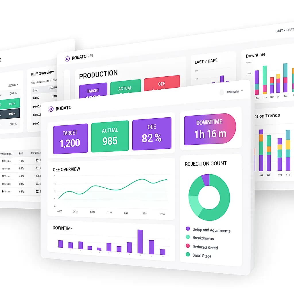
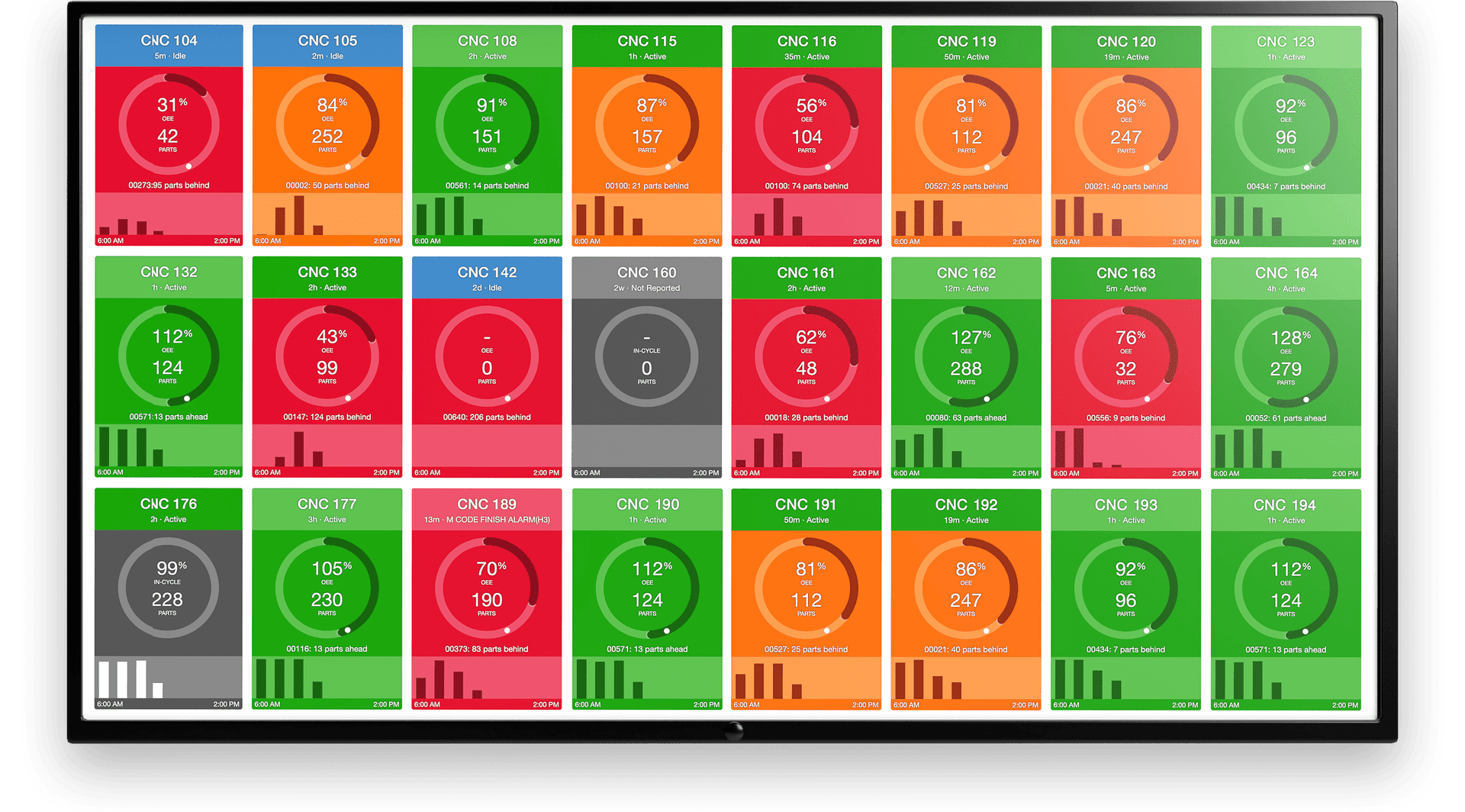
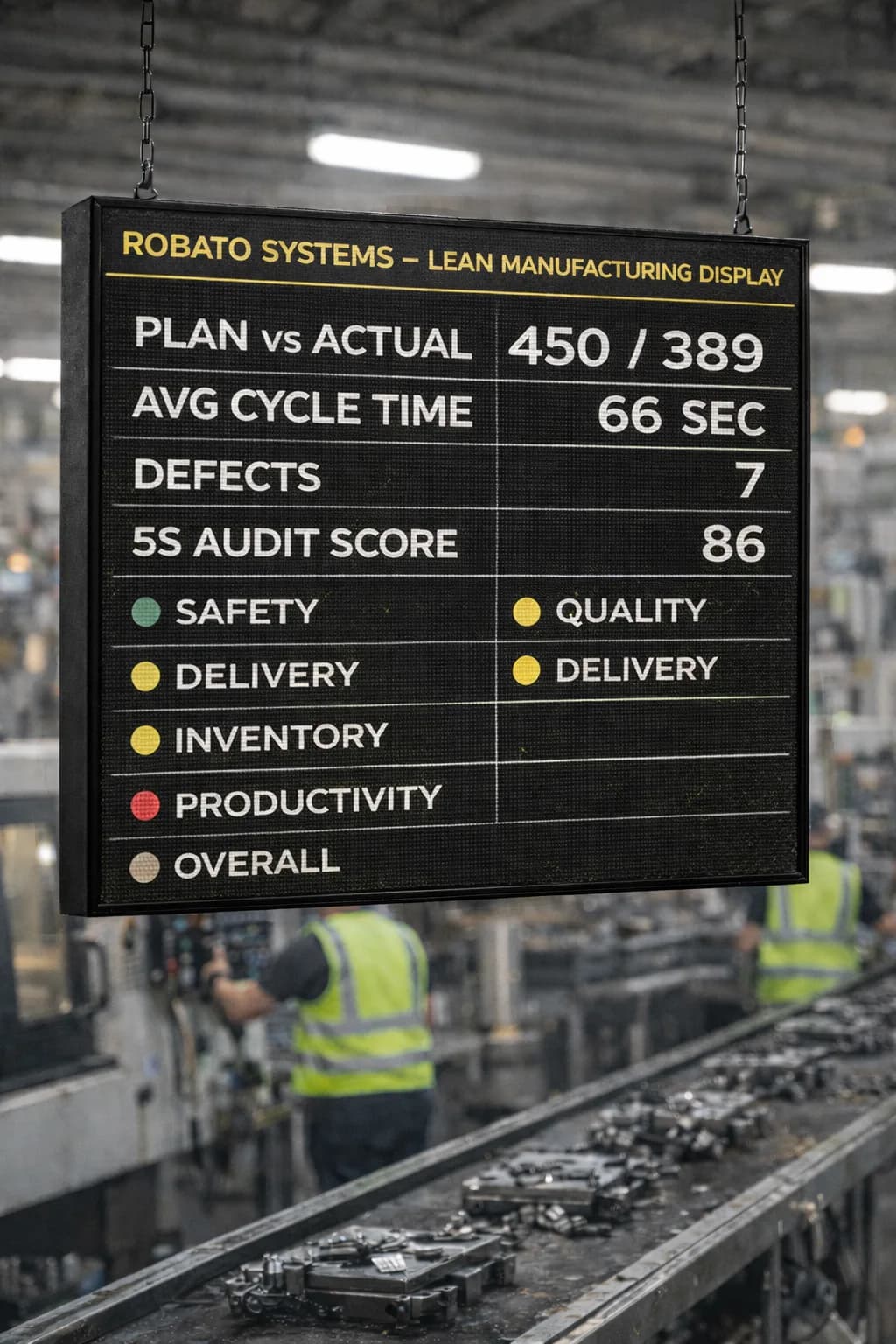
Depending on the implementation, dashboards may display:
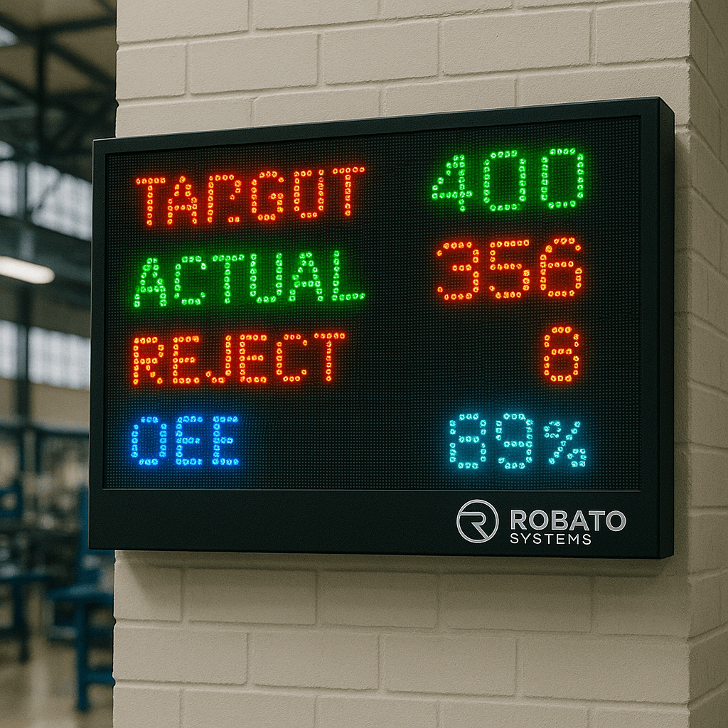
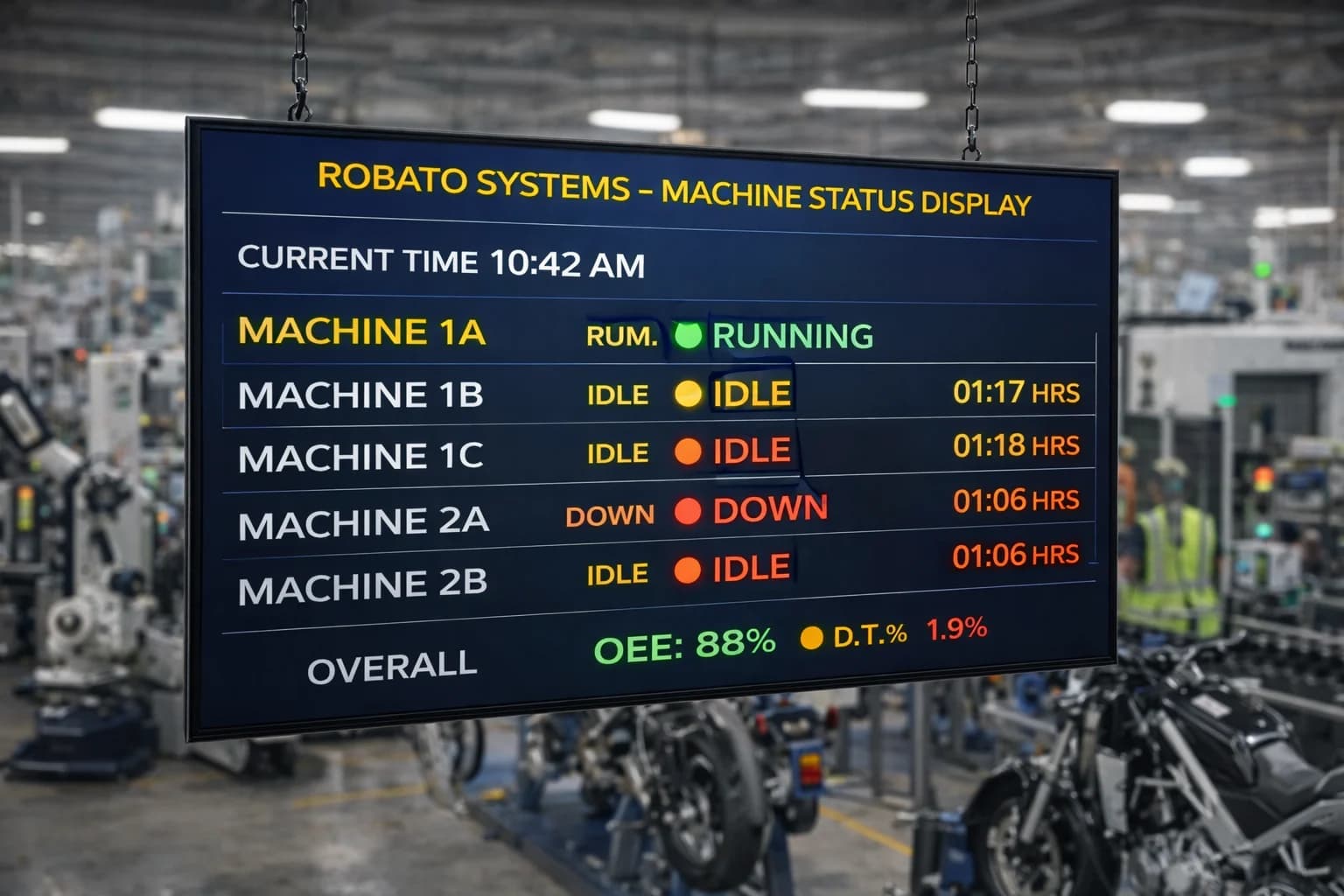
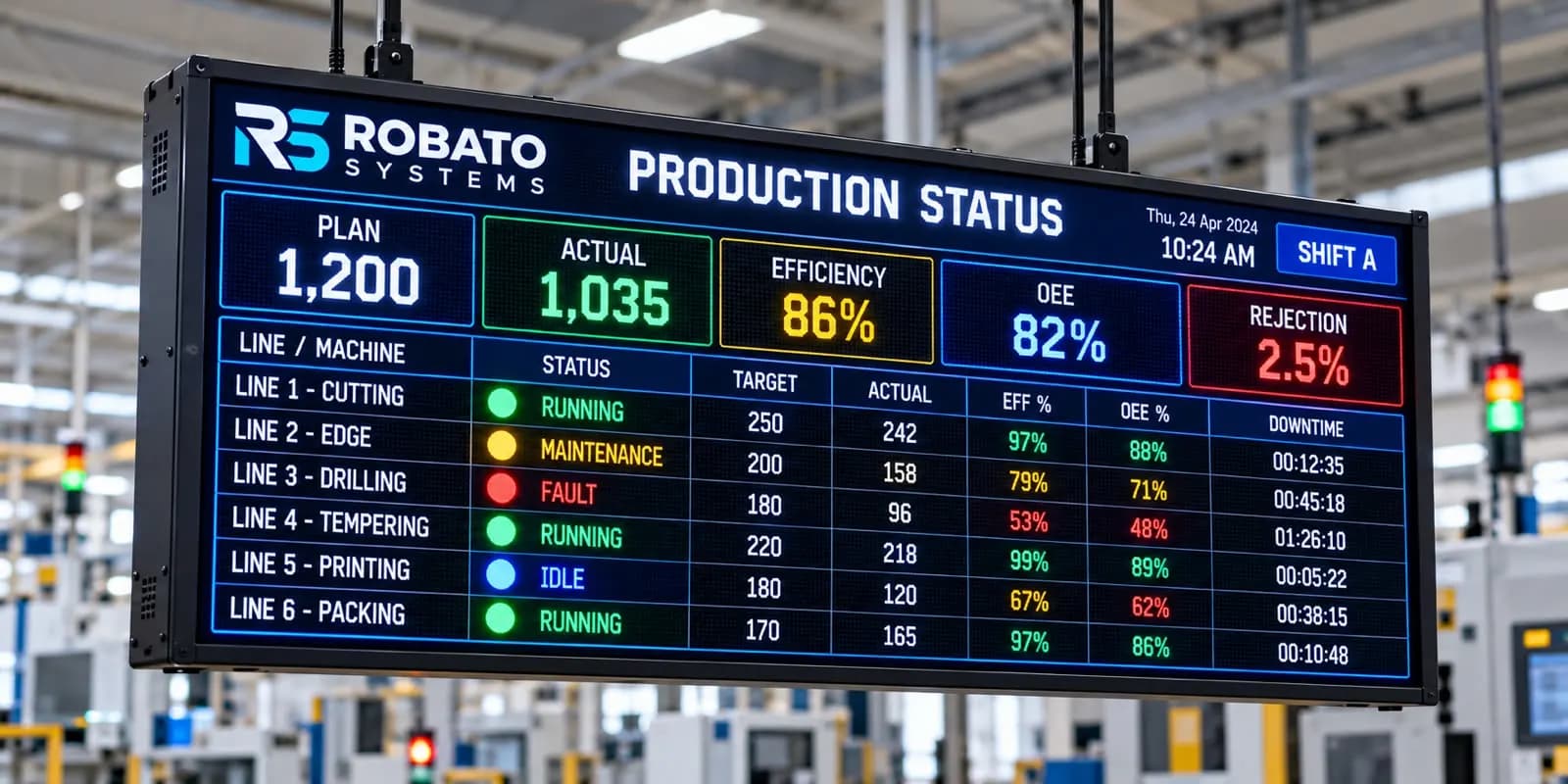
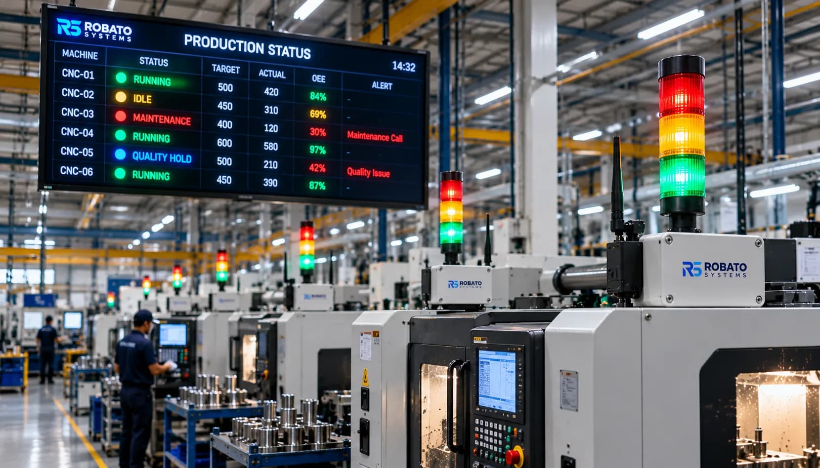
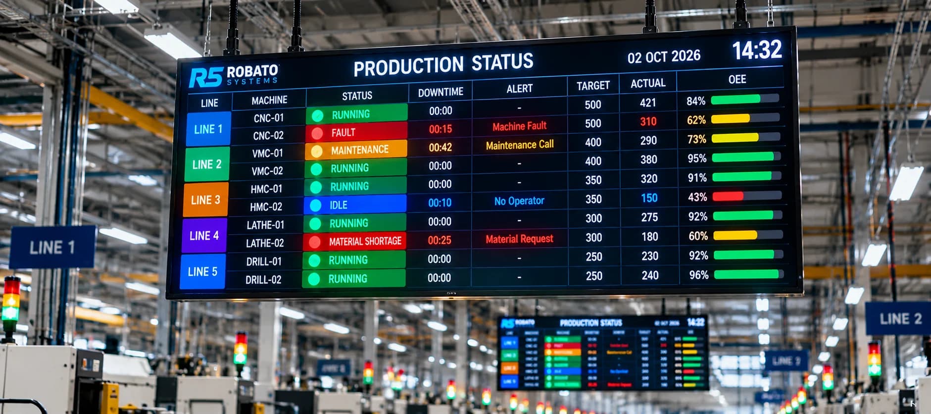
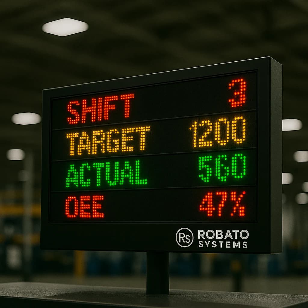
Live machine status
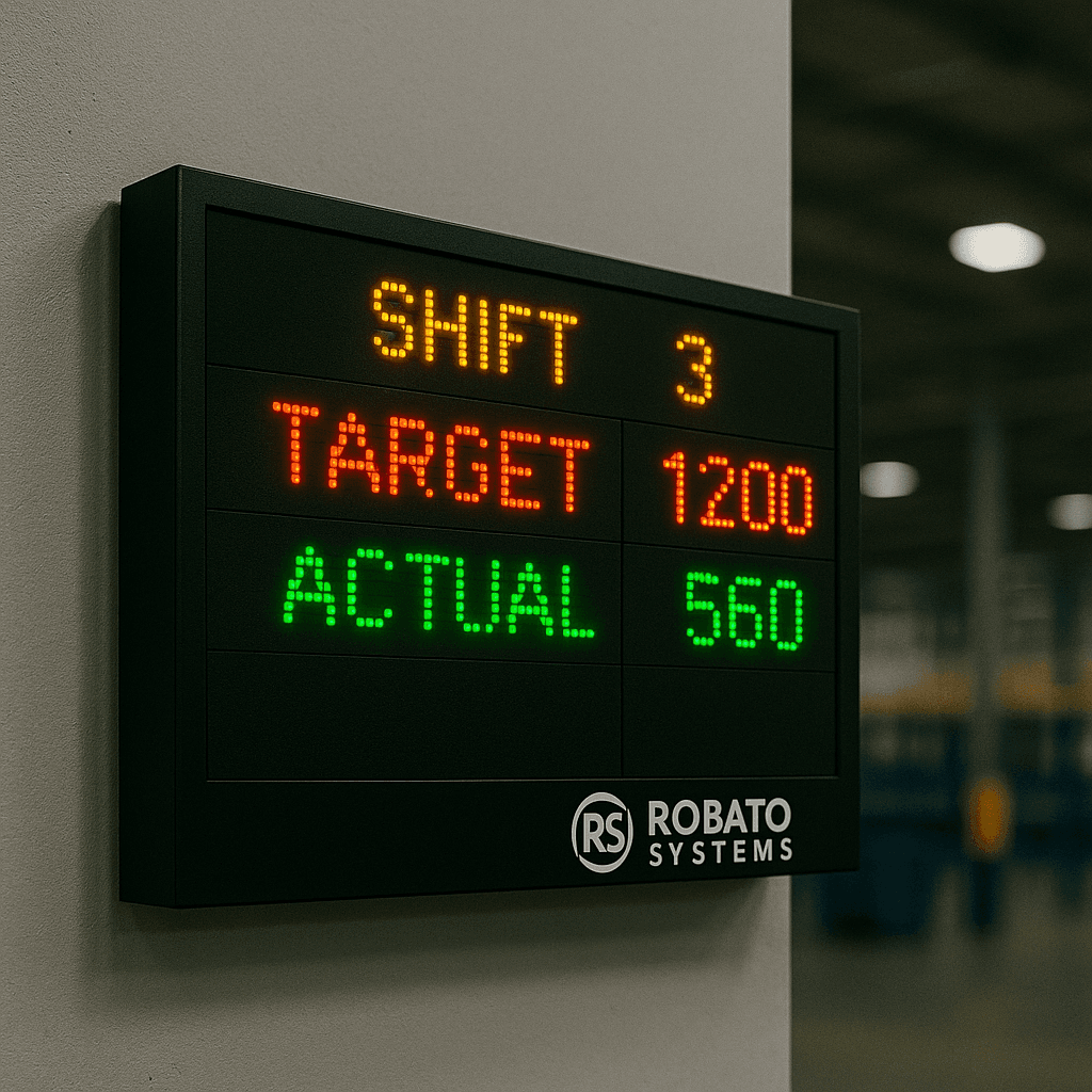
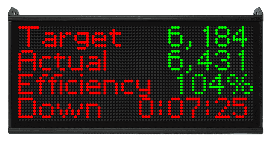
Production counts
Shift-wise output
Machine downtime
Cycle time
OEE
Historical production trends
A connected production monitoring software platform can bring machine-level information into a centralized view for production teams.
How to Implement CNC Data Collection in an Existing Factory
Implementing data collection across an entire factory requires planning. Starting with a focused pilot can help manufacturers validate the approach before expanding it.
Step 1: Identify the Machines
Prepare an inventory of CNC machines, including:
Manufacturer and model
Controller type and version
Machine age
Available communication interfaces
Existing PLCs and sensors
Network connectivity
This information helps determine which machines can support direct integration and which may require external data acquisition hardware.
Step 2: Define the Required Data Points
Identify what the production team actually needs to monitor.
A practical starting list may include:
Machine status
Part count
Cycle time
Alarm information
Downtime duration
Shift-wise production
Additional information can be included once the basic collection process is working reliably.
Step 3: Select the Appropriate Collection Method
Evaluate each machine separately.
A modern CNC controller may provide the required information through a native interface. Another machine may expose only basic PLC signals, while older equipment may require external sensors.
Avoid assuming that every machine supports the same communication method.
Step 4: Establish Connectivity
Configure the required network connections, gateways, communication interfaces, and access permissions.
For production environments, connectivity should be designed with the factory's IT and operational technology teams.
Read-only access should be preferred when the monitoring application only needs to collect information.
Step 5: Configure Data Mapping
Map the collected signals and values to meaningful machine information.
For example:
A controller state becomes a machine operating state.
A cycle-complete pulse becomes a production event.
A counter register becomes a production quantity.
An alarm code becomes a recorded machine event.
Data mapping should include clear definitions, units, timestamps, and reset behaviour.
Step 6: Validate the Collected Data
Compare system readings with actual machine activity and production records.
Check whether:
Part counts match physical output.
Machine states change at the correct time.
Cycle durations are reasonable.
Alarm timestamps are accurate.
Counter resets are handled correctly.
Data remains consistent across shift changes.
Validation is essential before using collected information for production decisions or performance calculations.
Step 7: Expand Across the Factory
Once the pilot is stable, extend the implementation to additional machines.
Use consistent naming conventions, machine identifiers, data definitions, and integration standards wherever possible.
This makes it easier to compare information across departments and production lines.
Common Challenges in CNC Data Collection
Even with suitable hardware and software, manufacturers can face integration and data-quality challenges.
1. Different CNC Controller Manufacturers
Factories often operate machines from multiple manufacturers, each with different communication capabilities.
Solution: Use a flexible architecture that supports native controller interfaces, PLC connections, industrial gateways, and compatible interoperability standards.
2. Legacy CNC Machines
Older machines may not expose digital data through modern interfaces.
Solution: Evaluate available PLC signals, electrical outputs, and suitable external sensors. An industrial gateway or data acquisition module can help connect these machines to the monitoring platform.
3. Inconsistent Machine Status Signals
Different machines may use different signals to represent similar operating conditions.
Solution: Define a common machine-state model and document how each machine's signals map to that model.
4. Inaccurate Production Counts
A machine cycle does not always correspond to one finished component. Some cycles produce multiple parts, while rejected components may also need to be recorded separately.
Solution: Validate counter logic against the actual manufacturing process and maintain a clear distinction between cycles, produced parts, and accepted parts.
5. Network Interruptions
Connectivity issues can interrupt data transmission and create gaps in production records.
Solution: Use gateways with local buffering and appropriate retry mechanisms. Monitor communication health and define how missing data should be identified.
6. Cybersecurity and Access Control
Connecting production equipment to monitoring networks introduces additional security considerations.
Solution: Apply network segmentation, access control, secure authentication, appropriate encryption, controlled remote access, and regular security reviews. Avoid unnecessary write access to machine controllers.
7. Missing Production Context
Machine signals can indicate that equipment has stopped, but they may not explain why.
Solution: Combine automatic collection with operator-entered downtime reasons and production-order information.
How CNC Data Collection Supports OEE Monitoring
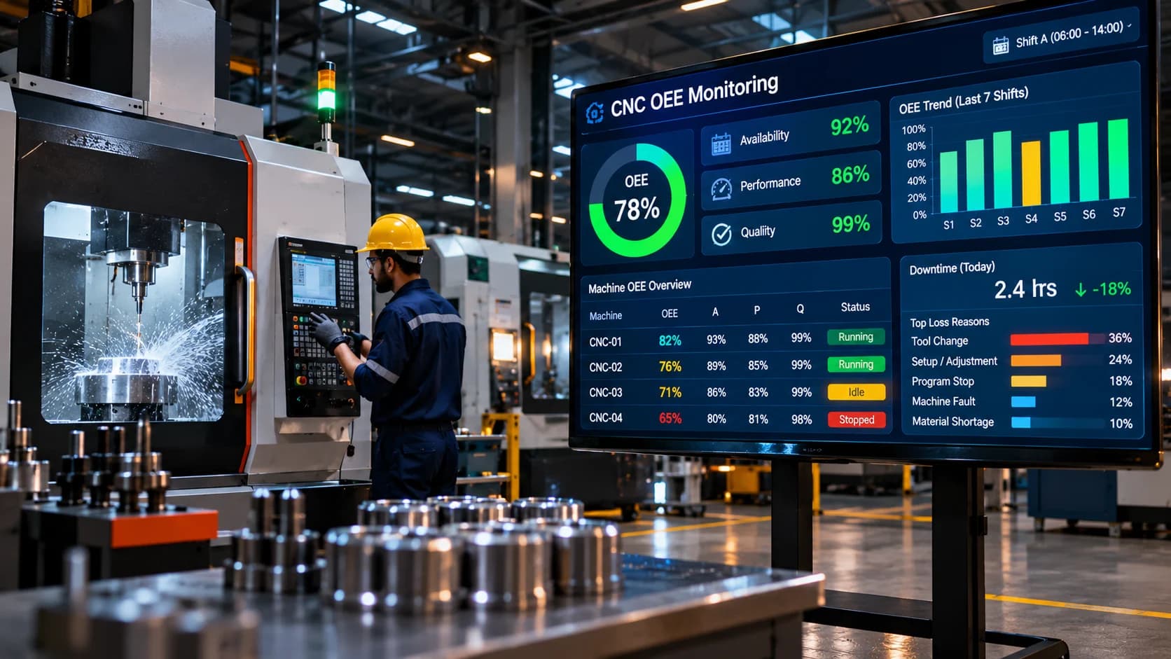
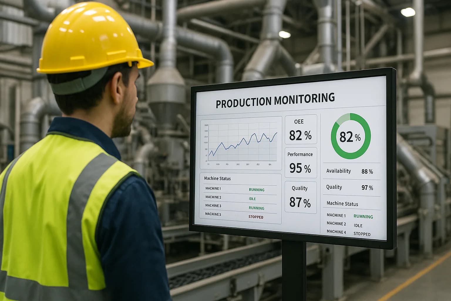
CNC data collection provides the information required to calculate and analyse Overall Equipment Effectiveness.
OEE evaluates three dimensions:
Availability: How much of the planned production time the machine was available to operate.
Performance: How closely the machine's actual operating speed matched its expected speed.
Quality: What proportion of produced parts met the required quality standards.
A CNC data collection system can provide machine-state events, operating time, cycle information, and production counts.
Quality information may require an additional source, such as inspection records, quality systems, or operator entries.
The standard formula is:
OEE = Availability × Performance × Quality
For example, a machine may have high availability but still produce fewer parts than expected because of longer cycle times. Another machine may produce the expected quantity but generate a higher number of rejected components.
Collecting the right information makes these differences visible.
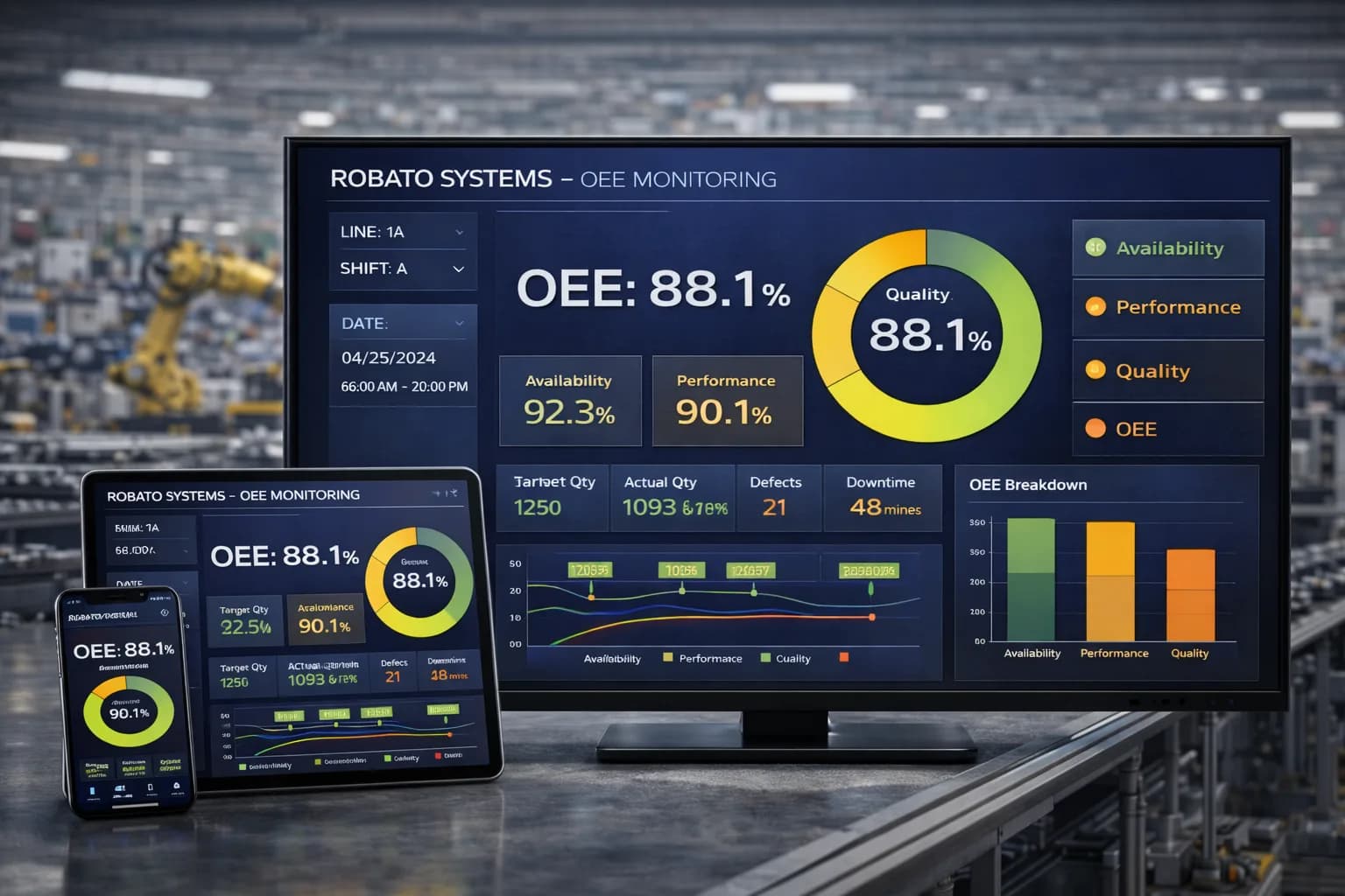
To understand how these measurements work together, explore Robato's OEE monitoring system.
Benefits of Integrating CNC Data with an IIoT Platform
Once CNC information is collected and standardized, it can be used across different production monitoring applications.
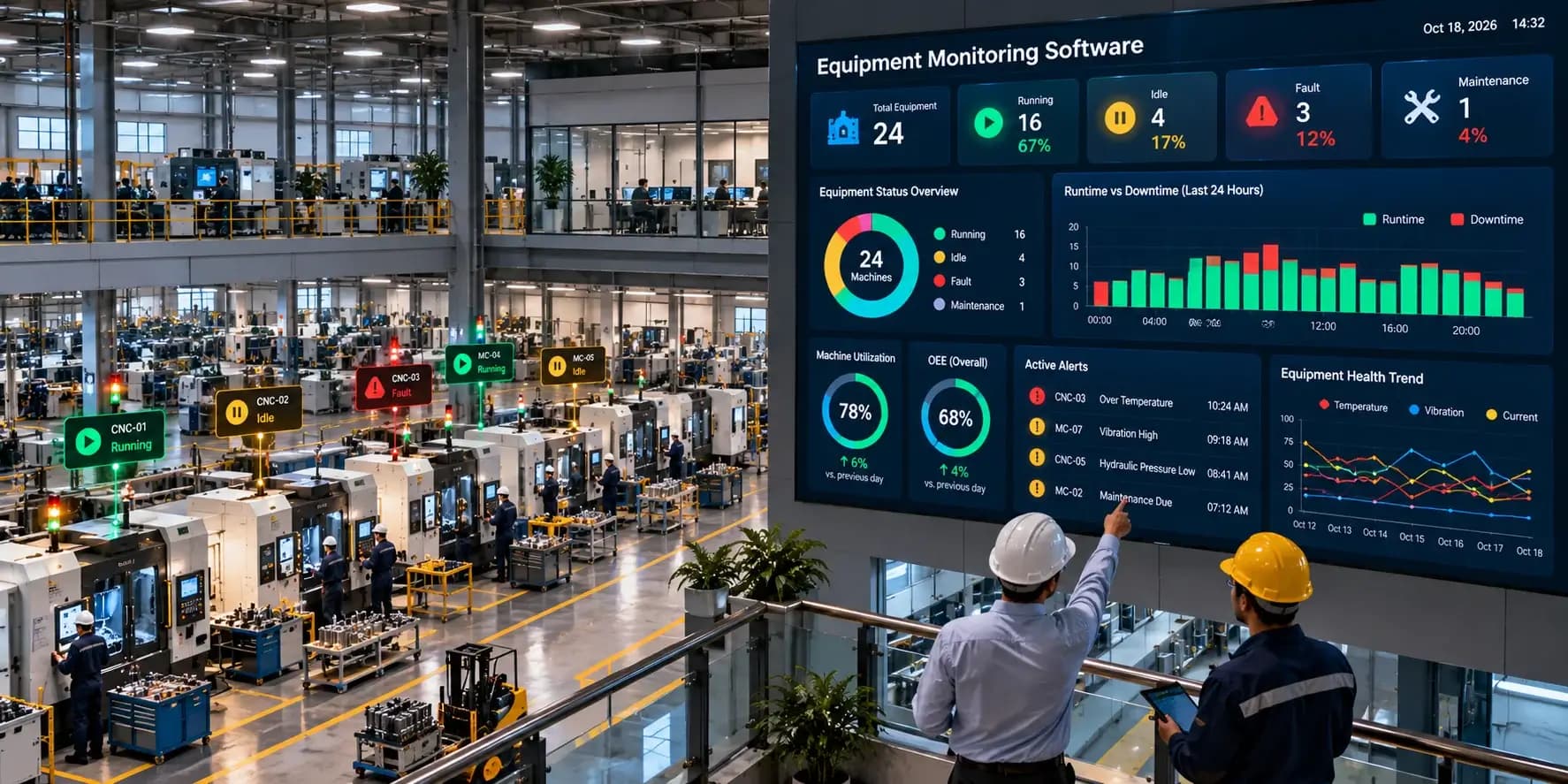
An Industrial Internet of Things platform can connect machine-level data with centralized dashboards and reporting systems.
Key benefits include:
Centralized Machine Visibility
Production teams can view multiple connected CNC machines from one monitoring environment.
Faster Identification of Production Interruptions
Real-time status updates and alerts can help supervisors identify equipment interruptions and coordinate responses.
Historical Production Analysis
Stored information allows teams to compare machine activity across shifts, days, and production periods.
Improved Resource Planning
Production managers can use machine utilization and output information to understand equipment availability and identify potential scheduling constraints.
Better Maintenance Insights
Machine alarms, operating hours, and selected condition measurements can support maintenance planning and equipment investigations.
Scalable Factory Connectivity
A gateway-based architecture can make it easier to connect additional machines and data sources as the factory expands.
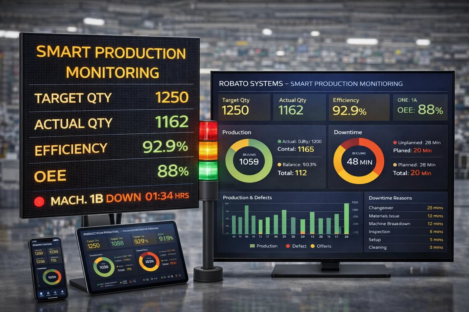
Manufacturers can also explore smart production monitoring to understand how connected equipment, data acquisition, and centralized monitoring work together.
CNC Data Collection for Cloud and On-Premise Monitoring
Manufacturers can deploy CNC monitoring systems using cloud-based or on-premise infrastructure.
The appropriate choice depends on operational requirements, network policies, data governance, and IT capabilities.
Cloud-Based CNC Data Collection
A cloud-based architecture sends selected machine information to a cloud-hosted platform.
It can support centralized monitoring across multiple factory locations, remote access, and consolidated reporting.
A suitable cloud production monitoring solution can provide access to machine information through connected dashboards.
Cloud connectivity should be designed with appropriate authentication, encryption, network controls, and data policies.
On-Premise CNC Data Collection
An on-premise deployment stores and processes machine information within the manufacturer's local infrastructure.
It may be preferred when data must remain within the factory network or when the organization has specific operational and security requirements.
Both approaches can support machine monitoring. The final architecture should be selected according to the factory's infrastructure and business requirements.
Best Practices for Reliable CNC Data Collection
To build a dependable system, manufacturers should follow a few important practices.
Start with essential data points: Focus first on machine status, production counts, cycle time, and alarms.
Check controller compatibility: Verify available interfaces before selecting integration hardware or software.
Use consistent machine identifiers: Every machine should have a unique and stable identifier.
Standardize machine states: Apply common definitions for running, idle, stopped, setup, and alarm conditions.
Validate production counts: Confirm how cycles, parts, and rejected components are represented.
Maintain accurate timestamps: Synchronize device and gateway clocks to support reliable event analysis.
Use local buffering where needed: Protect against temporary communication interruptions.
Secure machine connectivity: Apply appropriate network segmentation and access permissions.
Document data mappings: Maintain clear records of signals, registers, units, and event definitions.
Review data quality regularly: Monitor missing readings, duplicate events, unexpected values, and communication failures.
These practices help ensure that the collected information remains useful as more machines and production lines are connected.
Frequently Asked Questions About CNC Data Collection
1. What is CNC data collection?
CNC data collection is the process of capturing operational information from CNC machines, including machine status, production counts, cycle time, alarms, and selected process parameters. The information is transferred to a monitoring platform for production visibility and analysis.
2. How is data collected from CNC machines?
Data can be collected through CNC controller interfaces, PLCs, external sensors, digital input/output modules, industrial gateways, and operator-entry systems. The appropriate method depends on the machine's available interfaces and required information.
3. Can data be collected from older CNC machines?
Yes. Older machines can often be connected using available PLC signals, electrical outputs, external sensors, or suitable data acquisition hardware. The exact approach depends on the machine's electrical design and accessible signals.
4. What is the difference between CNC data acquisition and CNC data collection?
The terms are closely related. Data acquisition generally refers to capturing signals and measurements from equipment, while data collection can include acquisition, transmission, storage, validation, and organization of the information for monitoring and analysis.
5. What is MTConnect in CNC monitoring?
MTConnect is a manufacturing equipment interoperability standard that defines a structured way to represent and access machine information. It can help compatible CNC equipment and adapters expose operational data to monitoring applications.
6. What is the role of OPC UA in CNC data collection?
OPC UA provides a standardized industrial communication architecture for exchanging structured information between compatible equipment and applications. It can support secure communication between CNC-related controllers, PLCs, gateways, and monitoring software.
7. Can CNC data collection work without an internet connection?
Yes. A local or on-premise data collection architecture can operate within the factory network without requiring continuous internet connectivity. Cloud-based synchronization, if required, can be handled separately.
8. Can CNC machine data be used to calculate OEE?
Yes. Machine-state information, production counts, cycle-time data, and quality records can provide the inputs required for OEE calculations. Accurate definitions and reliable data sources are important for meaningful results.
9. How often should CNC machine data be collected?
The collection frequency depends on the data type and monitoring objective. Machine-state changes and production events may require event-based capture, while certain process measurements may be collected at configured intervals. The frequency should balance operational needs, controller capacity, and network load.
10. What is an industrial IoT gateway in CNC monitoring?
An industrial IoT gateway connects CNC controllers, PLCs, sensors, and other shop-floor devices to monitoring applications. It can collect, convert, process, buffer, and transmit information using supported industrial communication methods.
Conclusion
CNC data collection is a foundational part of connected manufacturing. It allows factories to move beyond isolated machine information and build a more complete understanding of production activity.
Whether information comes directly from CNC controllers, PLCs, external sensors, industrial gateways, MTConnect, or OPC UA, the goal remains the same: collect accurate and meaningful machine data that supports better operational decisions.
A well-designed implementation combines compatible collection methods, consistent data definitions, reliable connectivity, and a centralized monitoring platform. Starting with essential machine information and expanding gradually helps manufacturers build a scalable system without introducing unnecessary complexity.
For manufacturers planning to improve machine visibility, production tracking, and factory connectivity, Robato Systems'